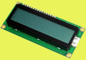
Nowadays most popular microcontrollers are working on 3.3V but many liquid crystal displays (LCDs) for them are usually on 5V, because they are centered on Hitachi’s de facto standard LCD controller – the HD44780 chip. Presented here is a simple yet effective trick to convert the standard 5V type LCD to a 3.3V one!
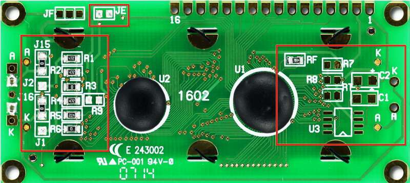
As you can see in the following photo some LCD modules have unpopulated footprints on the back for mounting a switched-capacitor voltage converter like the L7660 or MAX660 IC. Incase you have the same LCD circuit board, just add one MAX660 chip (U3),and two 10uF capacitors (C1-C2) to complete the hack. However, don’t forget to open the jumper J1 and close J3. That’s all.
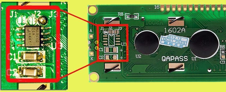
This little modification adds a negative charge pump converter to feed negative contrast voltage(V0) around 2.5V to the display electronics. This hack is necessary because the characters on the liquid crystal display type mentioned here becomes visible only when VDD-V0 ≥ 5V, where VDD is the operating voltage, and V0 is the contrast voltage of the LCD. Our simple maths gives an output value of V0 ≈ -2V, good for proper operation of the LCD at 3.3V. Take note, here the backlight lamp works as well on 3.3V, its brightness is slightly lower. This can be corrected by changing the value of its onboard current-limiter resistor (R8) if necessary.
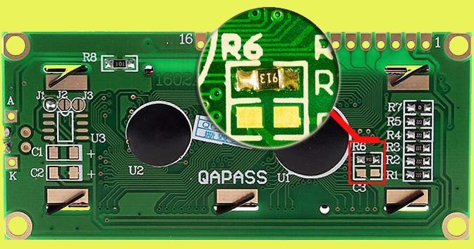
Another issue for concern (often when interfacing with fast microcontrollers) is the oscillator frequency of the LCD electronics, ie. when the supply voltage is lowered (5V to 3.3V), frequency of the built-in clock oscillator also falls down. The Rosc should be changed to a suitable value (from the typical 91KΩ – see next figure) for 3.3V if the extension of command execution time cannot be accepted.
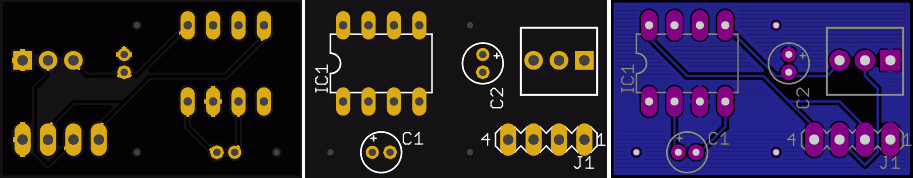
Even if your LCD is a different type i.e. without the vacant solder pads, you can still convert it to a 3.3V type with the help of the L7660 chip. For this, just build the following circuit on a small veroboard (or a customized pcb), and carefully interface it to your 5V LCD. However, your 5V LCD should be a type with HD44780 (or compatible) controller at its heart. The potentiometer (P1) in the given circuit is for contrast level adjustment of the display.
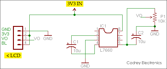
The pcb artwork of the adapter given here is for the quick reference of interested home pcb makers. Anyway, it’s not a scaled image; the actual pcb dimension is ~ 17.78 x 30.48mm!
While I was in the middle of my experiments, I got another 16×2 (5V) LCD module from a friend abroad (see next photo). It has the provision to mount L7660 chip (suits our needs) but we need to populate some more resistors/jumpers in addition to the usual 10uFx2 capacitors (see the marked area). Now I’m surfing the internet to get it running on 3.3V – stay tuned for updates…
I hope that you leave learned something new and have fun with this information. If you have any improvements, corrections/additions, please let me hear about them as well!
Useful Resources
- MAX660 Datasheet – http://www.ti.com/lit/ds/symlink/max660.pdf
- L7660 Datasheet – https://www.intersil.com/content/dam/Intersil/documents/icl7/icl7660.pdf
- HD44780U Datasheet – https://www.sparkfun.com/datasheets/LCD/HD44780.pdf
Hello, did you have any success in converting that last LCD to 3.3V?
Marius: Sadly it’s in queue. I’ll try to post updates here just after this Xmas season. Thanks for the reminder.
Hi, did you manage to get the last LCD to work on 3.3v? Thanks.
hello,
please I buy 3,3V type LCD on ebay, but I cant make it works, it seems like your (with solder jumper etc)
but I cant get any character, how you have connect contrast adjustmen plese?
can you hare some schematic.
thank you.
Regards
miroslav Decky: Could you please upload a photograph of the rear part (PCB) of the LCD?
Hello, I was searching also a methode to convert the 5V LCD to 3.3V and found a website in my country that is selling the 3.3V model hand they have a picture with the LCD from the back. The resolution is not so good but they seem to use 20 ohm resistor for backlight (R8), and maybe a 473 (47k) (it’s not very clear from the picture) as R6.
https://ibb.co/ZBzthRK
Hello
Thanks for the great project.
A vending machine that I’m trying to repair used the same 1602 lcd, with constant backlight on, but only uses 14 pins, leaving 15 and 16 disconnected.
How would I bridge the pads on the back to run +5v and ground straight to the backlight as opposed to my current solution which is a wire bridge between pin 1 and 16 and 3 and 15.
Hope that makes sense.
Bruno Ferreira: You are welcome! Glad to hear that it’s useful.
As you might noticed, Pin 15 is LED(A) and Pin 16 is LED(K), while Pin 1 is Gnd/0V and Pin 2 is VDD (5V 0r 3.3V). However the wire bridge between pin 15(K) and pin 3 (VEE-contrast) seems strange, Would you care to elaborate? Thanks!
Reference: http://media.nkcelectronics.com/datasheet/LCM1602A-NSW-BBW-33V33.pdf
Thank you for your imput.
The machine display lead has only got pin 1 through 14, pin 15 and 16 are not used but the backlight is still on. Is there a way to get 5v and ground on any footprint near the backight?
I will post a couple of pictures of the original screen as well I’d that helps.
Many thanks.
Sorry I meant 1 and 2 on earlier post
https://ibb.co/zm773hK
This is the lcd I need to replace. As you can see in the picture, pin 15 and 16 are not connected, however there’s power to the backlight. My question is would that be possible to replicate that with a lcd that you used above? Without any wires from pin 1 and 2 to pins 15 and 16?
Many thanks.
It seems that the back light pins are accessible. See extreme left side of the image you posted, and keep an eye (particularly) on the solder points and jumpers (that means A ,AJ2, JA & K, KJ1, JK, and so forth). Further, if you carefully go through the following datasheets of your BC1602A LCD, you can do many things with it. Thanks!
http://www.gamma.spb.ru/media/pdf/znakosinteziruyuschie-zhk-indikatory/BC1602A.pdf
https://www.es.co.th/Schemetic/PDF/BC1602.PDF
Very interesting site. I have 40×04 LCD display and positions for the chip and two capacitors are easily identifiable, but I cannot identify jumpers. Could you better explain where should the output of MAX660 (pin 5) go to, what are jumpers connecting in case of 5V and in 3.3V? I cannot see that from your picture?
Here is the picture of my device (but I could make better myself if it will be useful).
https://ae01.alicdn.com/kf/Hdc05a0bf34ef47968701184a7fee4887B/404-40X4-4004-Character-LCD-Module-Display-Screen-LCM-Yellow-Green-Blue-with-LED-Backlight-Build.jpg_q50.jpg
The strange thing is that V0 goes to jumper J1 and since J1 is open, it goes nowhere! I cannot believe it, V0 must be connected somewhere to make some impact, is it?? On the other hand, the output of MAX660 goes to resistor position R9 (which is empty). Everything is very confusing. If I understand right V0 pin should be below 0V to work, but how is output of MAX660 helping to pull the voltage down?
Best regards
@Marko: Thanks for your comment. You may refer this datasheet https://www.phidgets.com/productfiles/3655/3655_0/Documentation/3655_0_Datasheet.pdf I’ll come back with more fine details, after a couple of days.. BTW I couldn’t see the parts MAX660 and Rg, pointed by you, anywhere here. Hope you elaborate that!
Let me elaborate: I would like to know what is going on when you switch from 5V to 3.3V. My hypothesis is that something like this should happen:
http://www.pinteric.com/voltage.png
When you VDD=5V, V0=0.5, so you simply use outside voltage divider. However, when you use VDD=3.3V, V0=-1.2V. If you want to go below 0V, you need -3,3V from MAX660 pin 5, so part of voltage divider must be of the PCB.
I need to know how this works on your PCB so I could find solutions for my PCB.
@Marko: Prime theme of this post is the build of a negative charge pump converter to feed negative contrast voltage (V0) around to the display electronics (as clearly described in the 3rd paragraph).
Now I don’t have the parts used in this 2-years old post handy. Moreover, I’m looking for something different for a revision. So, I can’t provide more assistance right now. Sorry about that!
I wonder if anyone has ever tested this modification on a LCD1602 with an integrated I2C adapter on it. Typically the I2C adapter contains a potentiometer to adjust the contrast
Carlos: As you might noticed, usually an 8-Bit I/O Expander chip (PCF8574) is used in the 12C adapter circuit. Apart from the contrast adjust trimpot, you can see that there’s an onboard jumper to switch power to the backlight. So, to control the backlight intensity, you can remove the jumper and apply an external voltage to the header pin.
Anyway, I haven’t done the hack described in this post yet. Thanks!
So I received the necessary components today so I can populate the missing parts.
I removed the I2C board so I can access all pins and make the necessary changes. Do you have a schematic of the LCD board, I’m struggling to figure out what the three jumpers do so that I can connect the potentiometer correctly to pin Vo
Carlos: I do not have any backup data of this post published before 3 years. Sorry! I hope you Google next time 🙂
In the end I didn’t need the schematic but still managed to implement the hack. Follow these steps :
1. Desolder the I2C board and the potentiometer on that board
2. Add the missing components to the LCD board
3. Add a wire from C2 to I2C board
4. Bend the right leg of the potentionmeter and remove the pad to which it used to connect
5. Solder everything back and connect the wire to the bent leg
https://ibb.co/cYTMW4c
https://ibb.co/8Xrdgh2
https://ibb.co/TMwS7Jg