Добрый день.
Собрал в протеусе схемку
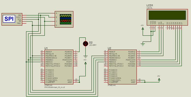
Вот
ссылка на проект протеуса.
Первый МК отсылкает файлы, второй принимает.
Проверяю отладчиком и осцилом - байты передаются.
Но принимающий МК никак не реагирует!! Прерывание по SPI не срабатывает((
Привожу коды.
МК-передатчик:
Chip type : ATmega8
Program type : Application
Clock frequency : 10,000000 MHz
Memory model : Small
External SRAM size : 0
Data Stack size : 256
************************************************** ***/
#include ‹mega8.h›
#include ‹delay.h›
// SPI interrupt service routine
interrupt [SPI_STC] void spi_isr(void)
{
unsigned char data;
data=SPDR;
// Place your code here
}
void write_config_data (unsigned int config_word){
PORTB.0=0; // nCS
SPDR=config_word/256;
while (SPSR.7!=1){};
SPDR=config_word%256;
while (SPSR.7!=1){};
PORTB.0=1; // nCS
}
// Declare your global variables here
void main(void)
{
// Declare your local variables here
// Input/Output Ports initialization
// Port B initialization
// Func7=In Func6=In Func5=Out Func4=In Func3=Out Func2=Out Func1=In Func0=In
// State7=T State6=T State5=0 State4=T State3=0 State2=0 State1=T State0=T
PORTB=0x00;
DDRB=0x2C;
// Port C initialization
// Func6=In Func5=In Func4=In Func3=In Func2=In Func1=In Func0=In
// State6=T State5=T State4=T State3=T State2=T State1=T State0=T
PORTC=0x00;
DDRC=0x00;
// Port D initialization
// Func7=In Func6=In Func5=In Func4=In Func3=In Func2=In Func1=In Func0=In
// State7=T State6=T State5=T State4=T State3=T State2=T State1=T State0=T
PORTD=0x00;
DDRD=0x01;
// Timer/Counter 0 initialization
// Clock source: System Clock
// Clock value: Timer 0 Stopped
TCCR0=0x00;
TCNT0=0x00;
// Timer/Counter 1 initialization
// Clock source: System Clock
// Clock value: Timer 1 Stopped
// Mode: Normal top=FFFFh
// OC1A output: Discon.
// OC1B output: Discon.
// Noise Canceler: Off
// Input Capture on Falling Edge
// Timer 1 Overflow Interrupt: Off
// Input Capture Interrupt: Off
// Compare A Match Interrupt: Off
// Compare B Match Interrupt: Off
TCCR1A=0x00;
TCCR1B=0x00;
TCNT1H=0x00;
TCNT1L=0x00;
ICR1H=0x00;
ICR1L=0x00;
OCR1AH=0x00;
OCR1AL=0x00;
OCR1BH=0x00;
OCR1BL=0x00;
// Timer/Counter 2 initialization
// Clock source: System Clock
// Clock value: Timer 2 Stopped
// Mode: Normal top=FFh
// OC2 output: Disconnected
ASSR=0x00;
TCCR2=0x00;
TCNT2=0x00;
OCR2=0x00;
// External Interrupt(s) initialization
// INT0: Off
// INT1: Off
MCUCR=0x00;
// Timer(s)/Counter(s) Interrupt(s) initialization
TIMSK=0x00;
// Analog Comparator initialization
// Analog Comparator: Off
// Analog Comparator Input Capture by Timer/Counter 1: Off
ACSR=0x80;
SFIOR=0x00;
SPCR=0x53;
SPSR=0x00;
// Clear the SPI interrupt flag
#asm
in r30,spsr
in r30,spdr
#endasm
// Global enable interrupts
#asm("sei")
delay_ms(500);
SPDR=0x2A;
delay_ms(500);
SPDR=0x2C;
delay_ms(500);
SPDR=0x2D;
delay_ms(500);
SPDR=0x1A;
delay_ms(500);
SPDR=0x1C;
delay_ms(500);
SPDR=0x1D;
PORTD.0=1;
while (1)
{
// Place your code here
};
}
МК-приемник:
Chip type : ATmega8
Program type : Application
Clock frequency : 10,000000 MHz
Memory model : Small
External SRAM size : 0
Data Stack size : 256
************************************************** ***/
#include ‹mega8.h›
#include ‹delay.h›
// Alphanumeric Module functions
#asm
.equ __lcd_port=0x12 ;PORTD
#endasm
#include ‹lcd.h›
unsigned char data;
// SPI interrupt service routine
interrupt [SPI_STC] void spi_isr(void)
{
data=SPDR;
/*
// Place your code here
count_3++;
Bytes[count_3]=data;
if (count_3==3)
{
count_3=0;
}
*/
lcd_putchar(data);
//lcd_putchar(SPDR);
}
// Declare your global variables here
void main(void)
{
// Declare your local variables here
// Input/Output Ports initialization
// Port B initialization
// Func7=In Func6=In Func5=In Func4=Out Func3=In Func2=In Func1=In Func0=In
// State7=T State6=T State5=T State4=0 State3=T State2=T State1=T State0=T
PORTB=0x00;
//DDRB=0x10;
DDRB=0x2C;
// Port C initialization
// Func6=In Func5=In Func4=In Func3=In Func2=In Func1=In Func0=In
// State6=T State5=T State4=T State3=T State2=T State1=T State0=T
PORTC=0x00;
DDRC=0x00;
// Port D initialization
// Func7=In Func6=In Func5=In Func4=In Func3=In Func2=In Func1=In Func0=In
// State7=T State6=T State5=T State4=T State3=T State2=T State1=T State0=T
PORTD=0x00;
DDRD=0x00;
// Timer/Counter 0 initialization
// Clock source: System Clock
// Clock value: Timer 0 Stopped
TCCR0=0x00;
TCNT0=0x00;
// Timer/Counter 1 initialization
// Clock source: System Clock
// Clock value: Timer 1 Stopped
// Mode: Normal top=FFFFh
// OC1A output: Discon.
// OC1B output: Discon.
// Noise Canceler: Off
// Input Capture on Falling Edge
// Timer 1 Overflow Interrupt: Off
// Input Capture Interrupt: Off
// Compare A Match Interrupt: Off
// Compare B Match Interrupt: Off
TCCR1A=0x00;
TCCR1B=0x00;
TCNT1H=0x00;
TCNT1L=0x00;
ICR1H=0x00;
ICR1L=0x00;
OCR1AH=0x00;
OCR1AL=0x00;
OCR1BH=0x00;
OCR1BL=0x00;
// Timer/Counter 2 initialization
// Clock source: System Clock
// Clock value: Timer 2 Stopped
// Mode: Normal top=FFh
// OC2 output: Disconnected
ASSR=0x00;
TCCR2=0x00;
TCNT2=0x00;
OCR2=0x00;
// External Interrupt(s) initialization
// INT0: Off
// INT1: Off
MCUCR=0x00;
// Timer(s)/Counter(s) Interrupt(s) initialization
TIMSK=0x00;
// Analog Comparator initialization
// Analog Comparator: Off
// Analog Comparator Input Capture by Timer/Counter 1: Off
ACSR=0x80;
SFIOR=0x00;
SPCR=0x53;
SPSR=0x00;
// Clear the SPI interrupt flag
#asm
in r30,spsr
in r30,spdr
#endasm
// Global enable interrupts
#asm("sei")
// LCD module initialization
lcd_init(16);
PORTD.0=1;
lcd_gotoxy(0,0);
lcd_putsf("User char 0:");
lcd_gotoxy(0,1);
while (1)
{
lcd_putchar(data);
};
}